
| ftp.delorie.com/electronics/gR8C/ | search |
What is gR8C? The gR8C (pronounced "great, see?") standard is a hardware standard for interfacing R8C processors to host computers, both for programming them and for communicating with them. By standardizing, all gR8C-compatible projects can interact with each other and share their work.
The FT232R chip provides not only serial (heck, any usb chip can do that) but four unrelated controllable I/O pins. By connecting one of these to the MODE pin, the host PC can automatically put the R8C into serial mode 2, program the chip, and put it back into user mode.
The 18.432 MHz clock is a multiple of 16 times 115200, giving perfect baud rates at all supported speeds. An external clock source is also a requirement for serial mode 2. A fixed clock rate means gR8C-compatibile UART and timer libraries can be shared, without having to reconfigure for different clocks.
DTR on RESET serves two purposes - first, it allows the host PC to reset the board, both for programming and restart. Second, it makes the board act more like a peripheral - the board remains in reset until the PC connects to it, at which point the board starts running just as the PC is paying attention.
Use of serial mode 2 means that at least one of the UARTs is connected to the USB chip's uart, so a serial connection to the PC is always available.
Note that other FT232R pins may also be connected to the R8C chip - often, CTS/RTS - but these are not required.
The preference for other CBUS pins is as follows: CBUS0 is TxLED, CBUS1 is RxLED, CBUS3 is I/O (use unspecified), and CBUS4 is PWRON.
When the USB interface and R8C are on separate boards, there are two standard connector pinouts - the E8a pinout, and a six-pin serial-micro pinout. Both pinouts support 0.1 inch pitch (male on target) as well as 0.050 inch pitch (female on target) connectors. Note that only the Serial Mode 2 connection scheme is gR8C compatible; the Mode 3 connection is not.
When the USB interface and R8C are on separate boards, gR8C compatibility is determined for each board separately.
The gR8C standard does not specify any board power requirements. Boards that are USB-powered should comply with the USB standards. Boards using programming connectors (E8a or serial-micro) may be self-powered or connector-powered, providing the E8a/usb and r8c board are power-compatible.
Boards and software which comply with the gR8C standards may display the gR8C logo.
My sample flash tool provides a reference implementation in its uflash program.
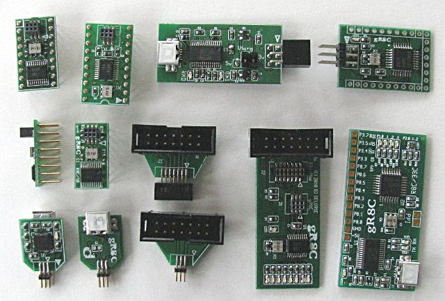
This first image is a range of gR8C-compatible boards, including
DIP adapters, connector demos, and both combined and split boards.
Also included are some E8a-mini socket
adapters.
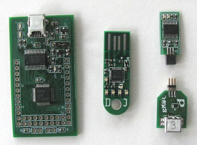
This second image is a range of non-gR8C-compatible boards
demonstrating some variation The rightmost pair is a serial mode 3
(single pin) pair. None of these boards include the 18.432 MHz
crystal, hence the "non-compatible" status.
| prev next webmaster | delorie software privacy |
| Copyright © 2010 | Updated Oct 2010 |